Building an Enterprise Network: Implementing VLANs, Inter-VLAN Routing, and Voice VLANs

In our previous post, we configured EIGRP to dynamically manage routing between sites. Now, we'll improve internal network segmentation by implementing VLANs in for our teams, configuring Inter-VLAN routing, and setting up Voice VLANs for office telephones.
This ensures that:
- Setting up a data vlan for our teams
- Inter-VLAN Routing allows necessary communication between teams.
- Voice VLANs provide a dedicated network for IP phones, ensuring high-quality voice traffic.
- Setting up DHCP server so we can automatically assign IP addresses to our devices.
I made a post about VLANs and Inter-VLANs earlier, so if you are an unfamiliar with VLANs and Inter-VLANS you can find it here.

You can also find the start of the "Building an Enterprise Network" here.

Setting the Scene
So I have been thinking lately on what this office environment actually is. I wanted to think of something that would have some real-world scenario to it, and also to make the process a little more interesting on what we are building.
So I decided to go with an Insurance Company. Not the flashiest company idea, however it gives us a good structure to go by and a way to expand it as we go along.
So the things are insurance company has:
- Main office in London
- Branch office in Manchester
- Data center in Glasgow.
- Insurance broker team, who sell insurance
- Renewal team for people who want to renew their insurance
- Management teams, IT teams and HR team.
Now we will be adding another access switch connected to our other access switch on London and Manchester site. We will be using the same switch as we have done previously. We need to do this because we are adding more PCs to our new teams.
This is what our network topology should look like when we are completed.
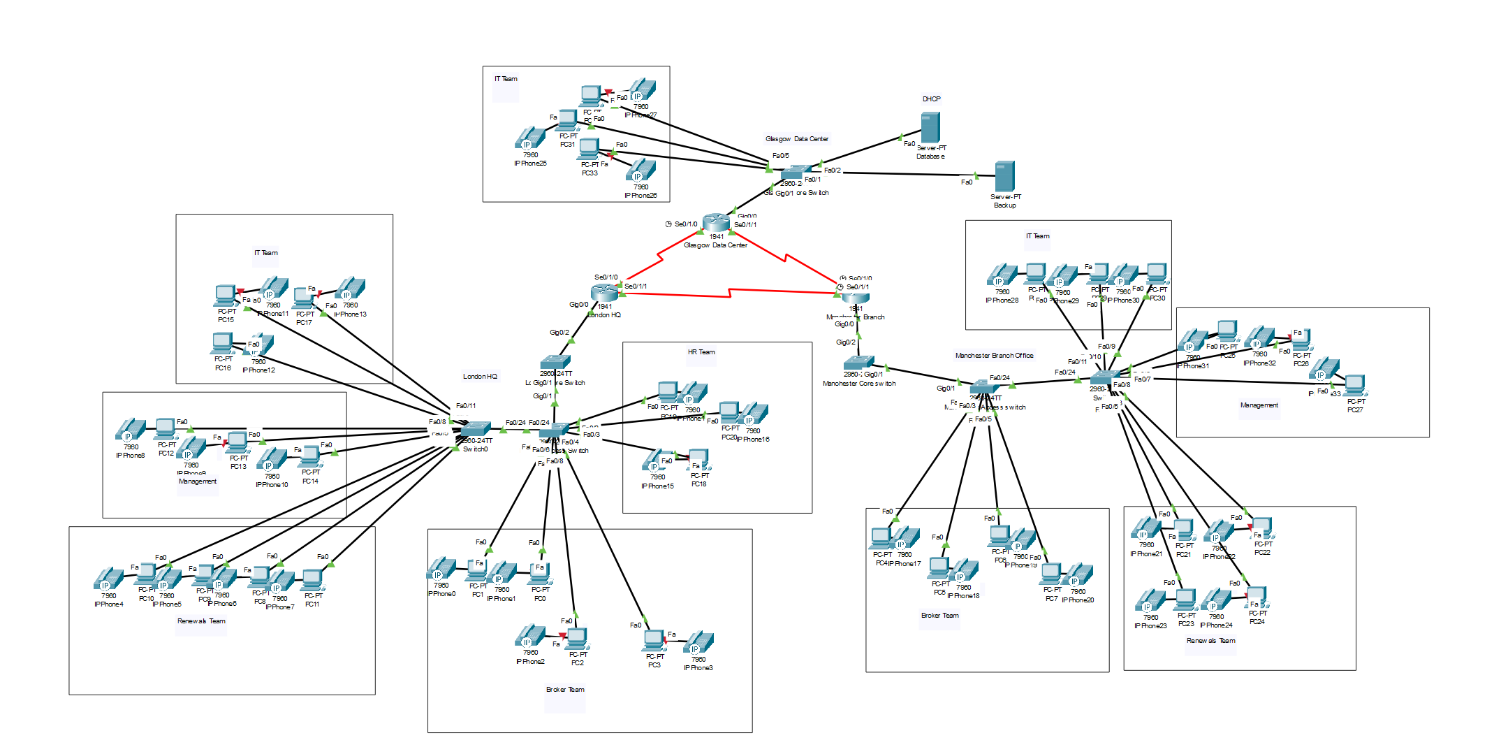
So now we have an idea of what the project actually looks like and what we will be building and designing, let's get to building it.
- Network Subnets
For simplicity, we will only be creating two VLANs. One for data and one for voice.
London (192.168.1.0/24
|
VLAN |
Purpose |
Subnet |
Gateway |
|
2 |
Data |
192.168.1.0/24 |
192.168.1.1 |
|
3 |
Voice |
192.168.11.0/24 |
192.168.11.1 |
Manchester Branch Office (192.168.2.0/24)
|
VLAN |
Purpose |
Subnet |
Gateway |
|
2 |
Data |
192.168.2.0/24 |
192.168.2.1 |
|
3 |
Voice |
192.168.12.0/24 |
192.168.12.1 |
Glasgow Data Center (192.168.3.0/24)
|
VLAN |
Purpose |
Subnet |
Gateway |
|
2 |
Data |
192.168.3.0/24 |
192.168.3.1 |
|
3 |
Voice |
192.168.13.0 |
192.168.13.1 |
- Configure VlANs
We need to add the two VLANs to the switches.
London Core Switch
London-Core-SW>enable
London-Core-SW#config terminal
London-Core-SW(config)#vlan 2
London-Core-SW(config-vlan)#name Data
London-Core-SW(config-vlan)#exit
London-Core-SW(config)#vlan 3
London-Core-SW(config-vlan)#name Voice
London-Core-SW(config-vlan)#exit
London-Core-SW(config)exit
London-Core-SW#write memory
Repeat these for Manchester and Glasgow.
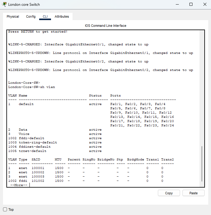
When finished, you can do a "show vlan" to see the newly created VLANs on the device.
- Assign VLANs to Ports
Now we need to assign our VLANs to the ports on our switch. To do this, we need to see which Pcs are plugged into which port on the switch and then configure them with the data VLAN and voice VLAN.
HR & Broker Team
London-Acc-SW2>enable
London-Acc-SW2#config terminal
London-Acc-SW2(config)#interface range fastEthernet 0/2-4
London-Acc-SW2(config-if-range)#switchport mode access
London-Acc-SW2(config-if-range)#switchport access vlan 2
London-Acc-SW2(config-if-range)#switchport voice vlan 3
London-Acc-SW2(config-if-range)#exit
London-Acc-SW2(config)#interface range fastEthernet 0/5-8
London-Acc-SW2(config-if-range)#switchport mode access
London-Acc-SW2(config-if-range)#switchport access vlan 2
London-Acc-SW2(config-if-range)#switchport voice vlan 3
London-Acc-SW2(config-if-range)#exit
London-Acc-SW2(config)#exit
London-Acc-SW2#write memory
You will need to do this for all the access switches.
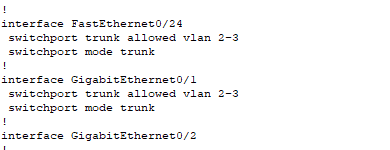
After you have done that, we will also need to configure our trunk ports on our access switches and also from the core switch to the router.
London Access Switch
London-Acc-SW2>enable
London-Acc-SW2#config terminal
London-Acc-SW2(config) interface fastEthernet0/24
London-Acc-SW2(config-if)#switchport mode trunk
London-Acc-SW2(config-if)#switchport trunk allowed vlan 2,3
London-Acc-SW2(config-if)#exit
London-Acc-SW2(config)#exit
London-Acc-SW2# write memory
London Core Switch → London Router
London-Core-SW>enable
London-Core-SW#config terminal
London-Core-SW(config)interface GigabitEthernet 0/2
London-Core-SWconfig-if)#switchport mode trunk
London-Core-SW(config-if)#switchport trunk allowed vlan 2,3
London-Core-SW(config-if)#exit
London-Core-SW(config)exit
London-Core-SW#write memory
You will need to do this on all the access switches and core switches on each site.
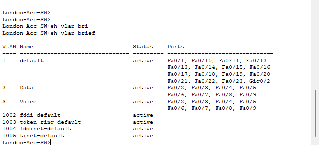
After you have done that, you can do a "show vlan brief" to see assigned ports. You can also do a "show run" to see the whole running-configuration of the switch.
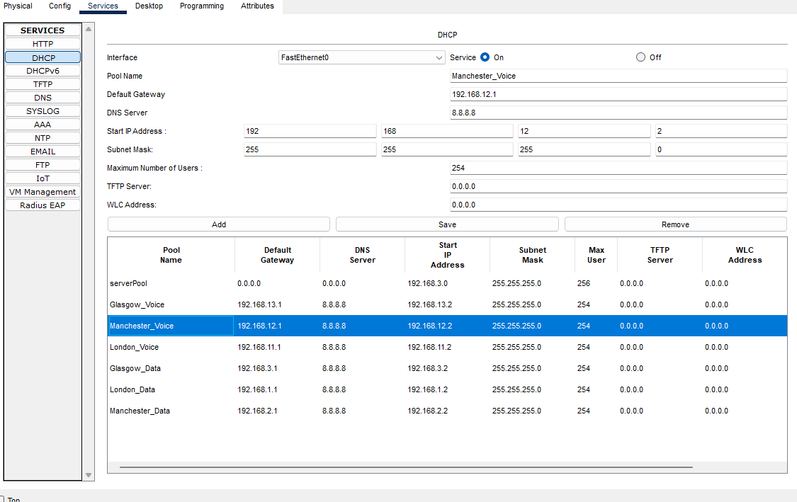
- Configuring the DHCP Server
For our DHCP server, I have added the DHCP service to our Database server.
If we click on our Database Server and go to Services, we can see DHCP on the left-hand side.
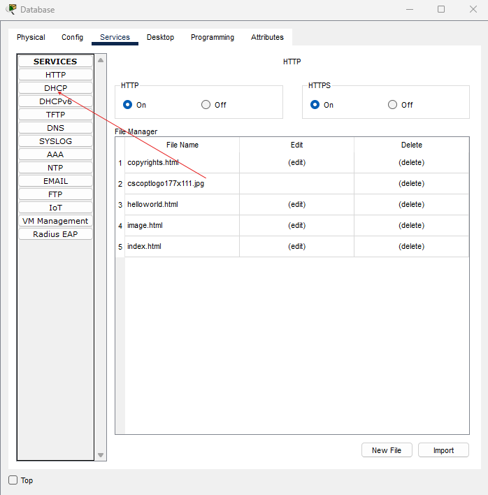
Make sure that the DHCP Service is ticked On.

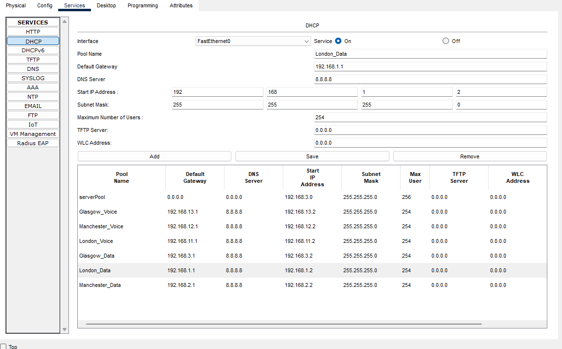
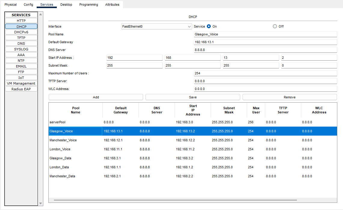
Here we need to add the IP address scopes for each site, so each device will be allocated the correct IP address range for their site.
London-Data
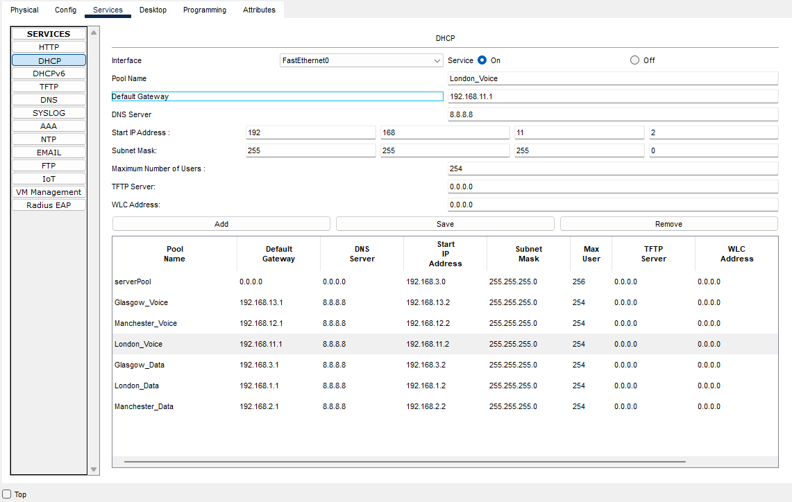
London-Voice
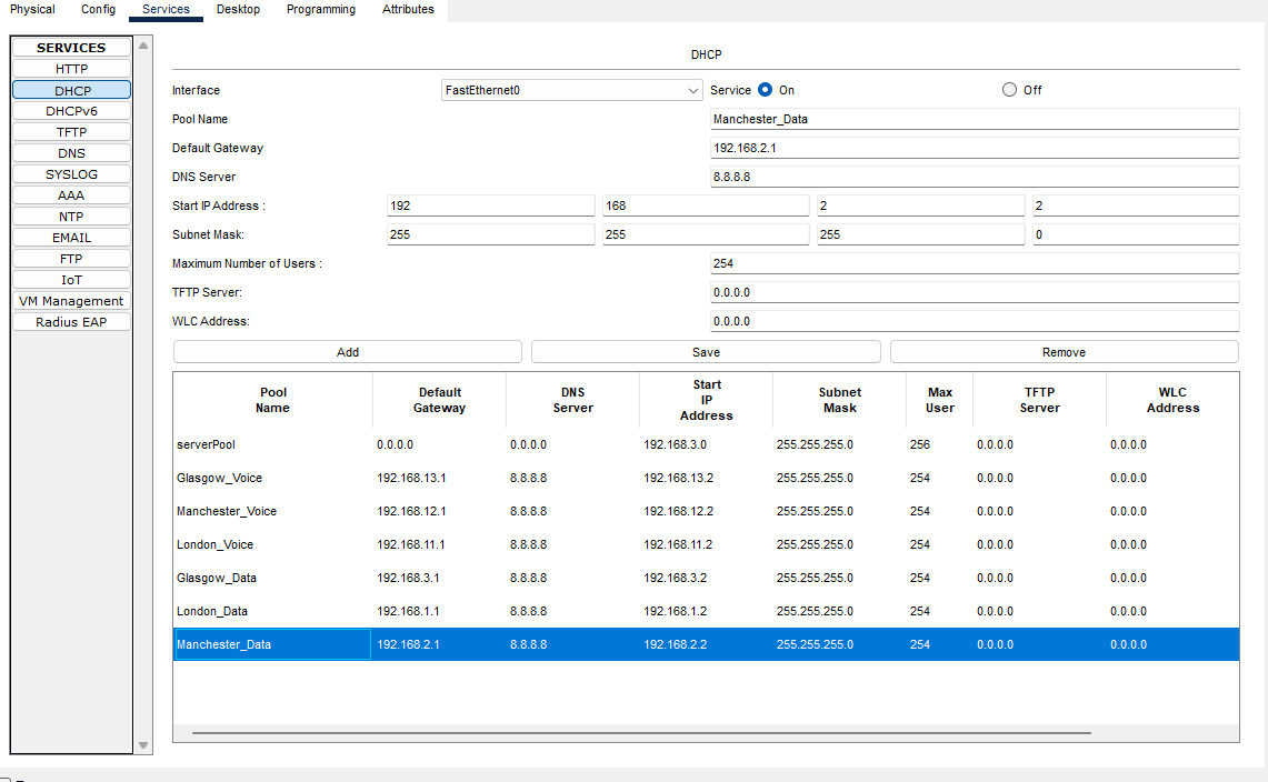
Manchester-Data
Manchester-Voice
Glasgow-Data
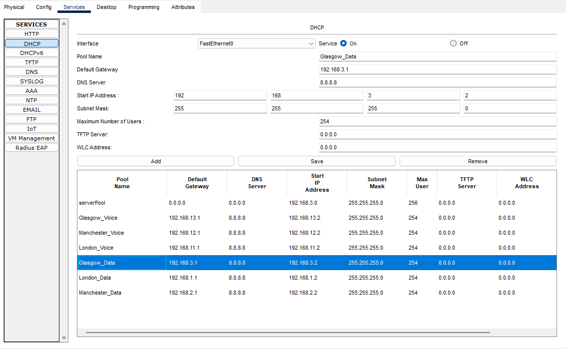
Glasgow-Voice
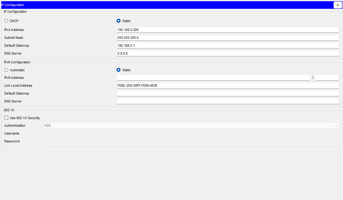
Now that we have configured all the DHCP scopes, we need to configure our Database server with a static IP address.
Set the IP address the same as the picture below
- Configure Inter-VLANs
Now that we have configured all the VLANs and assigned them to the correct ports on the switches, we need to configure Inter-VLANs on the Routers.
We will also be adding our DHCP server IP to our Inter-VLANs so that the routers can communicate to the DHCP server and pass the IP addresses from their correct scopes to their devices.
London Router
At the moment we have 192.168.1.1 on Gigabit Ethernet 0/0. We want to remove this so it does not conflict with our sub interface setup
London-HQ-RT>enable
London-HQ-RT>#configure terminal
London-HQ-RT(config)#interface gigabitEthernet0/0
London-HQ-RT(config-if)#no ip address
London-HQ-RT(config-if)#no shut down
London-HQ-RT(config-if)#exit
London-HQ-RT(config)#exit
London-HQ-RT#write memory
Now we have removed the IP address from the main interface, we can now configure the sub interfaces.
London-HQ-RT>enable
London-HQ-RT>#configure terminal
London-HQ-RT(config)#interface gigabitEthernet0/0.2
London-HQ-RT(config-subif)#encapsulation dot1Q 2
London-HQ-RT(config-subif)#ip address 192.168.1.1 255.255.255.0
London-HQ-RT(config-subif)#ip helper-address 192.168.3.200
London-HQ-RT(config-subif)#exit
London-HQ-RT(config)#interface gigabitEthernet0/0.3
London-HQ-RT(config-subif)#encapsulation dot1Q 3
London-HQ-RT(config-subif)#ip address 192.168.11.1 255.255.255.0
London-HQ-RT(config-subif)#ip helper-address 192.168.3.200
London-HQ-RT(config-subif)#exit
London-HQ-RT(config)#exit
London-HQ-RT>#write memory
Manchester Router
First remove the 192.168.2.1 on Gigabit Ethernet 0/0
Manchester-BR-RT>enable
Manchester-BR-RT>#configure terminal
Manchester-BR-RT(config)#interface gigabitEthernet0/0
Manchester-BR-RT(config-if)#no ip address
Manchester-BR-RT(config-if)#no shut down
Manchester-BR-RT(config-if)#exit
Manchester-BR-RT(config)#exit
Manchester-BR-RT#write memory
 Manchester-BR-RT>enable
 Manchester-BR-RT>#configure terminal
 Manchester-BR-RT(config)#interface gigabitEthernet0/0.2
 Manchester-BR-RT(config-subif)#encapsulation dot1Q 2
 Manchester-BR-RT(config-subif)#ip address 192.168.2.1 255.255.255.0
 Manchester-BR-RT(config-subif)#ip helper-address 192.168.3.200
 Manchester-BR-RT(config-subif)#exit
 Manchester-BR-RT(config)#interface gigabitEthernet0/0.3
 Manchester-BR-RT(config-subif)#encapsulation dot1Q 3
 Manchester-BR-RT(config-subif)#ip address 192.168.12.1 255.255.255.0
 Manchester-BR-RT(config-subif)#ip helper-address 192.168.3.200
 Manchester-BR-RT(config-subif)#exit
 Manchester-BR-RT(config)#exit
 Manchester-BR-RT>#write memory
Glasgow Router
  Glasgow-Data-RT>enable
    Glasgow-Data-RT>#configure terminal
    Glasgow-Data-RT(config)#interface gigabitEthernet0/0
    Glasgow-Data-RT(config-if)#no ip address
    Glasgow-Data-RT(config-if)#no shut down
    Glasgow-Data-RT(config-if)#exit
    Glasgow-Data-RT(config)#exit
    Glasgow-Data-RT#write memory
 Glasgow-Data-RT>enable
 Glasgow-Data-RT>#configure terminal
 Glasgow-Data-RT(config)#interface gigabitEthernet0/0.2
 Glasgow-Data-RT(config-subif)#encapsulation dot1Q 2
 Glasgow-Data-RT(config-subif)#ip address 192.168.3.1 255.255.255.0
 Glasgow-Data-RT(config-subif)#exit
 Glasgow-Data-RT(config)#interface gigabitEthernet0/0.3
 Glasgow-Data-RT(config-subif)#encapsulation dot1Q 3
 Glasgow-Data-RT(config-subif)#ip address 192.168.13.1 255.255.255.0
 Glasgow-Data-RT(config-subif)#exit
 Glasgow-Data-RT(config)#exit
 Glasgow-Data-RT>#write memory
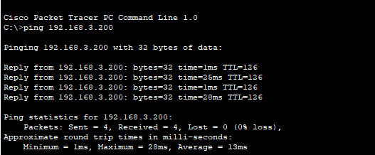
Now we have configured all the routers with Inter-VLANs & adding the DHCP IP address to the VLANs we should be able to ping the DHCP server from one of the routers.

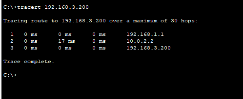
Let's do a trace route as well.
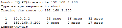
Yes, that as worked we can see that it's hitting 10.0.2.2 which is Glasgow serial link and then going to the DHCP server which is 192.168.3.200
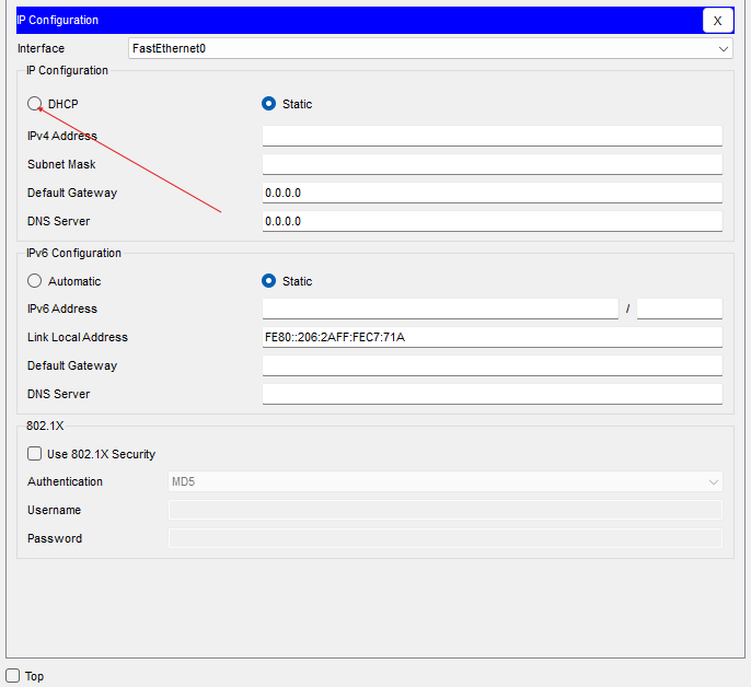
- Setting up PCs with DHCP
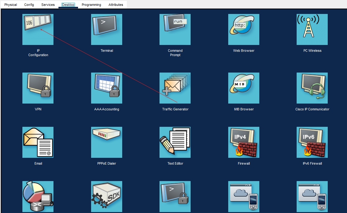
Now that we have our switches all setup, routers are set up and our DHCP server is configured, now it's time to set up our PCs for DHCP to see if the DHCP is working correctly.
Select a PC at one of the sites, and go to IP configuration.
Wait to see if the IP address is being allocated.
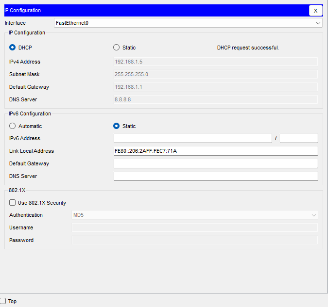
Perfect, our DHCP is working and so are our VLANs.
We can check this by doing a ping and a tracert to the DHCP server
We will need to enable DHCP on all PCs so that they can be allocated an IP address from our DHCP server.
Conclusion
We have configured the VLANS and Inter-VLANS on our devices, and also set up our DHCP Server to allocate IP addresses to our devices on each site.
Next we will configure our IP phones so they can also get an IP address from the DHCP and also dive into Access Control Lists.
I hope you enjoyed this guide and Happy Networking!