Designing an Enterprise Network: Laying the Foundation for Multi-Site Connectivity in Packet Tracer

In this blog series, we'll be building a complete enterprise network in Cisco packet tracer and expanding it as we go on. Our goal is to simulate a real-world network connecting multiple geographical sites: London (Headquarters), Manchester (Branch Office), and Glasgow (Data Center).
This first post focuses on designing the network, setting up the topology, and ensuring basic connectivity between the sites.
- Plan the Network Topology
To simulate a multi-site enterprise network, we'll use three locations:
- London HQ: Central site with core and access switches for employees.
- Manchester Branch: Branch office with core and access switches for employees.
- Glasgow Data Center: Hosting critical servers like databases and backups.
Devices and Links:
- London (HQ):
- 1 Router
- 2 Switches (Core and Access)
- 4 PCs
- Manchester (Branch Office):
- 1 Router
- 2 Switches (Core and Access)
- 4 PCs
- Glasgow (Data Center):
- 1 Router
- 1 Core Switch
- 2 Servers (Database and backup)
- WAN Links: Serial connection between routers to simulate WAN connectivity.
- Create the Network in Packet Tracer
1. Add Devices:
- Place routers, switches, PCs, and Servers for each site in the workspace.
- Router Models (1941)
- Switches (2960-24TT)
- Connect Devices:
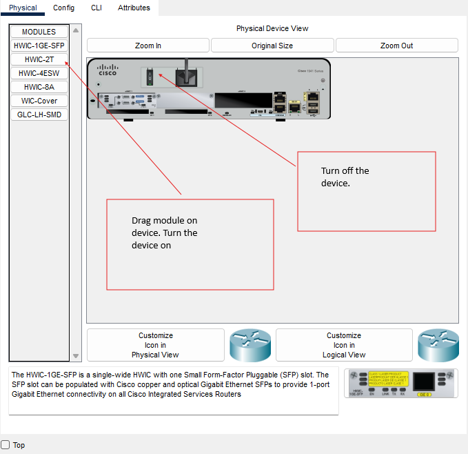
With the routers, we need to add the HWIC-2T module to the back of the device. This is to connect our serial links to each router. Click the router, go to Physical → Turn off device → Drag HWIC-2T to Device. Do this for each router.
- Use Ethernet Cables to connect PCs and switches.
- Use Serial DCE/DTE cables to connect the routers for WAN links.
- Label Everything:
- Clearly label each device to which site it represents.
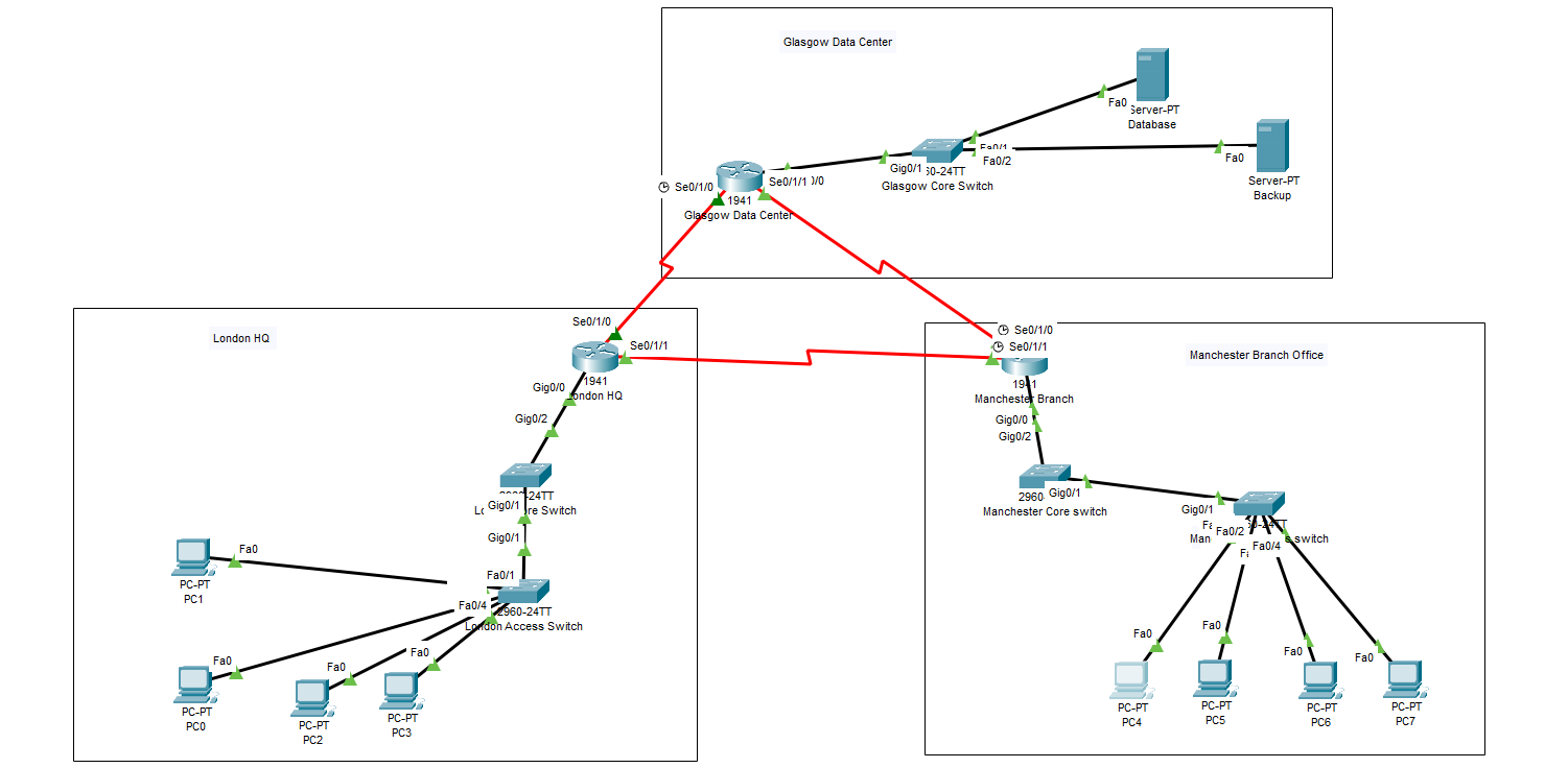
In the end, you should have something that looks like this:
- IP Addressing Plan
Here's the IP addressing schema for our network:
|
Site |
Subnet |
Device |
IP Address |
|
London HQ |
192.168.1./24 |
Router LAN |
192.168.1.1 |
|
|
|
PCs (1 - 4) |
102.168.1.2 - 192.168.1.5 |
|
|
10.0.1.0/30 |
WAN to Manchester |
10.0.1.1 |
|
|
10.0.2.0/30 |
WAN to Glasgow |
10.0.2.1 |
|
Manchester |
192.168.2.0/24 |
Router LAN |
192.168.2.1 |
|
|
|
PCs (1 - 4) |
192.168.2.2 - 192.168.2.5 |
|
|
10.0.1.0/30 |
WAN to London |
10.0.1.2 |
|
|
10.0.3.0/30 |
WAN to Glasgow |
10.0.3.1 |
|
Glasgow |
192.168.3.0/24 |
Router LAN |
192.168.3.1 |
|
|
|
Database Server |
192.168.3.2 |
|
|
|
Backup Server |
192.168.3.3 |
|
|
10.0.2.0/30 |
WAN to London |
10.0.2.2 |
|
|
10.0.3.0/30 |
WAN to Manchester |
10.0.3.2 |
- Configure Basic IP Settings
On PCs and Servers:
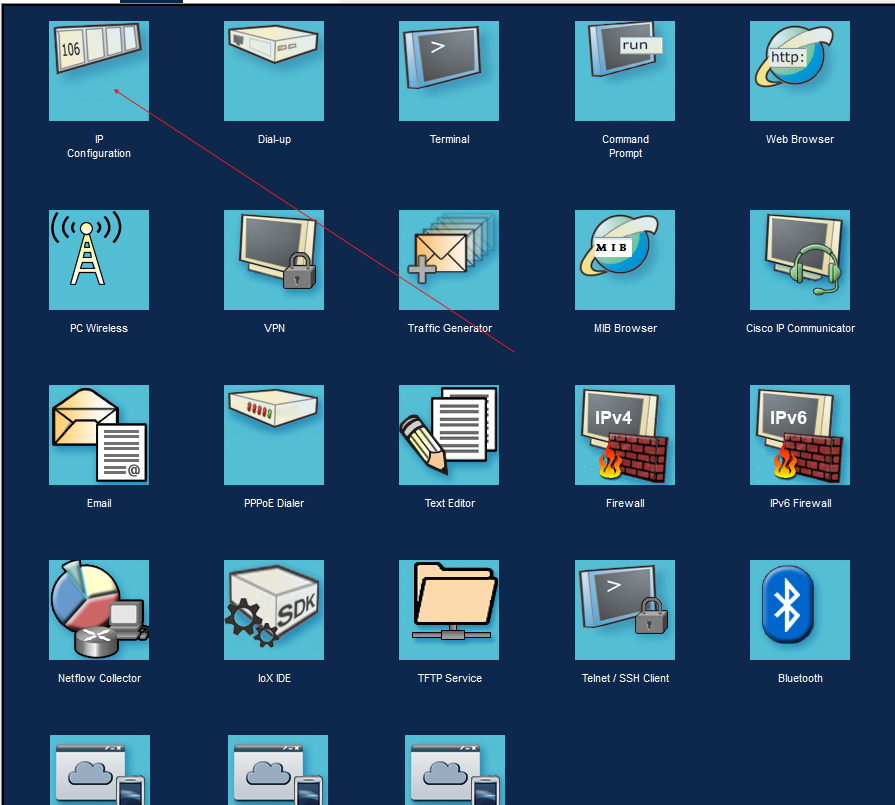
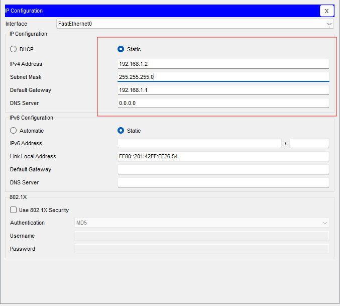
- Go to each PC/Server and Assign:
- An IP Address.
- A Subnet Mask (255.255.255.0 for all)
- A Default Gateway (router LAN interface IP)
Do this for each PC. Follow the IP Address scheme for each Pc in the list and for the correct default gateway for each site.
Do the same for the servers in Glasgow.
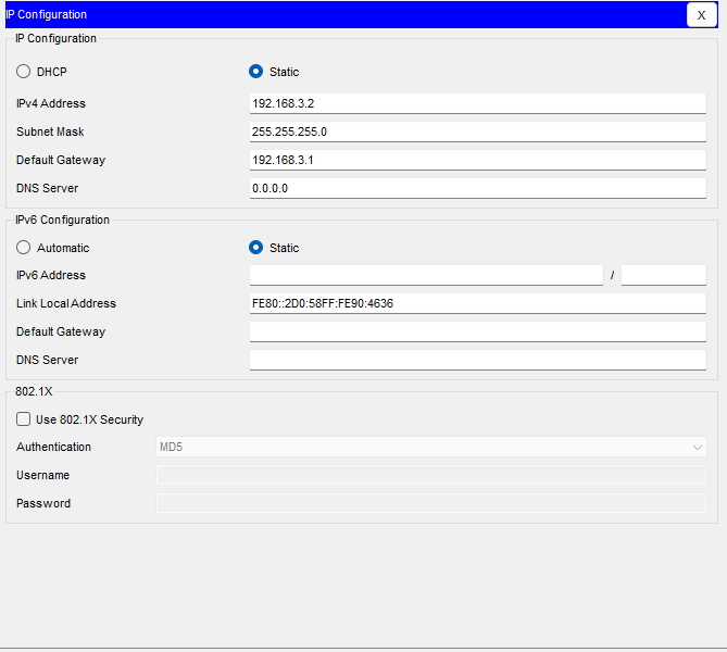
Now with the PC and Server IP addresses configured statically we can now configure each router with the default gateway.
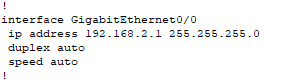
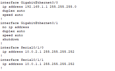
London Router:
For me, Gigabit Ethernet 0/0 is the main feed from my Core switch to the router.
London-HQ-RT>enable
London-HQ-RT>config t
London-HQ-RT(config)interface Gigabit Ethernet 0/0
London-HQ-RT(config-if)ip address 192.168.1.1 255.255.255.0
London-HQ-RT(config-if)no shut
London-HQ-RT(config-if)exit
London-HQ-RT(config)exit
London-HQ-RT>write memory
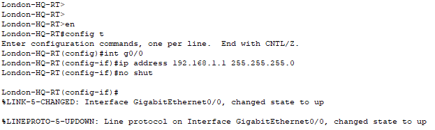
We can see the interface change its state from down to up.
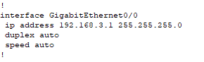
Now we need to do this for each router. Check the default gateway from the IP Address scheme and configure each Gigabit Ethernet port that goes from the router to each core switch.
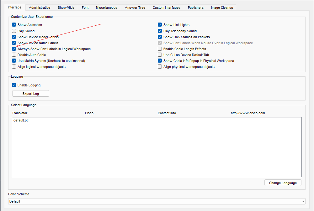
You can set up Packet Tracer to show you the ports each Ethernet cable is plugged into by going to Options → Preferences → Tick "Always Show Port Labels in Logical Workspace"
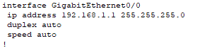
After configuration on each router, we can do a show run command to see the interface.
Now you have all default gateways and PCs configured. Try and see if you can ping each routers' gateway for their correct site. Don't worry about pinging from one site to another, as that will not work yet. Just ping the router that site belongs to.
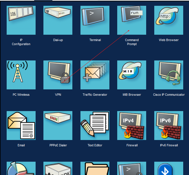
Go to a PC in London and open up the Command Prompt
Let's Ping the London Routers Default gateway
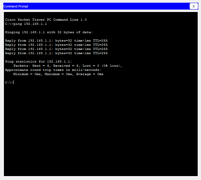
We now know that PCs in London can ping the London router. Do this for each site
- Configure WAN interfaces.
Now we need to configure the Wan Links that connects each router together. Here, we will be following our IP Address Scheme to set up our configuration correctly.
London:
|
10.0.1.0/30 |
WAN to Manchester |
10.0.1.1 |
|
10.0.2.0/30 |
WAN to Glasgow |
10.0.2.1 |
London-HQ-RT>enable
London-HQ-RT>config t
London-HQ-RT(config)config t
London-HQ-RT(config)interface serial 0/1/0
London-HQ-RT(config-if)ip address 10.0.2.1 255.255.255.252
London-HQ-RT(config-if)no shut
London-HQ-RT(config-if)exit
London-HQ-RT(config)interface serial 0/1/1
London-HQ-RT(config-if)ip address 10.0.1.1 255.255.255.252
London-HQ-RT(config-if)no shut
London-HQ-RT(config-if)exit
London-HQ-RT(config)exit
London-HQ-RT>write memory
Manchester:
|
10.0.2.0/30 |
WAN to London |
10.0.2.2 |
|
10.0.3.0/30 |
WAN to Manchester |
10.0.3.2 |
Manchester-BR-RT>enable
Manchester-BR-RT>config t
Manchester-BR-RT(config)interface serial 0/1/0
Manchester-BR-RT(config-if)ip address 10.0.3.1 255.255.255.252
Manchester-BR-RT(config-if)clock rate 64000
Manchester-BR-RT(config-if)no shut
Manchester-BR-RT(config-if)exit
Manchester-BR-RT(config)interface serial 0/1/1
Manchester-BR-RT(config-if)ip address 10.0.1.2 255.255.255.252
Manchester-BR-RT(config-if)clock rate 64000
Manchester-BR-RT(config-if)exit
Manchester-BR-RT(config)exit
Manchester-BR-RT>write memory
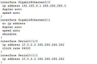
Glasgow:
|
10.0.2.0/30 |
WAN to London |
10.0.2.2 |
|
10.0.3.0/30 |
WAN to Manchester |
10.0.3.2 |
Glasgow-Data-RT>enable
Glasgow-Data-RT>config
Glasgow-Data-RT(config)interface serial 0/1/0
Glasgow-Data-RT(config-if)ip address 10.0.2.2 255.255.255.252
Glasgow-Data-RT(config-if)clock rate 64000
Glasgow-Data-RT(config-if)no shut
Glasgow-Data-RT(config-if)exit
Glasgow-Data-RT(config)interface serial 0/1/1
Glasgow-Data-RT(config-if)ip address 10.0.3.2 255.255.255.252
Glasgow-Data-RT(config-if)no shut
Glasgow-Data-RT(config-if)exit
Glasgow-Data-RT(config)exit
Glasgow-Data-RT>write memory
With all the configuration setup, we can do a show run command to see what our configuration looks like on each router.
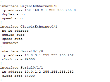
The clock rate command used only on the DCE (Date Communication Equipment) side of a serial connection. If you are getting an error "This command applies only to DCE interfaces," it means that the interface you are trying to configure is the DTE (Data Terminal Equipment) side of the connection.
In Packet Tracer, the DCE/DTE designation is determined automatically when you connect two devices with a serial cable. The DCE side is responsible for providing the clocking.
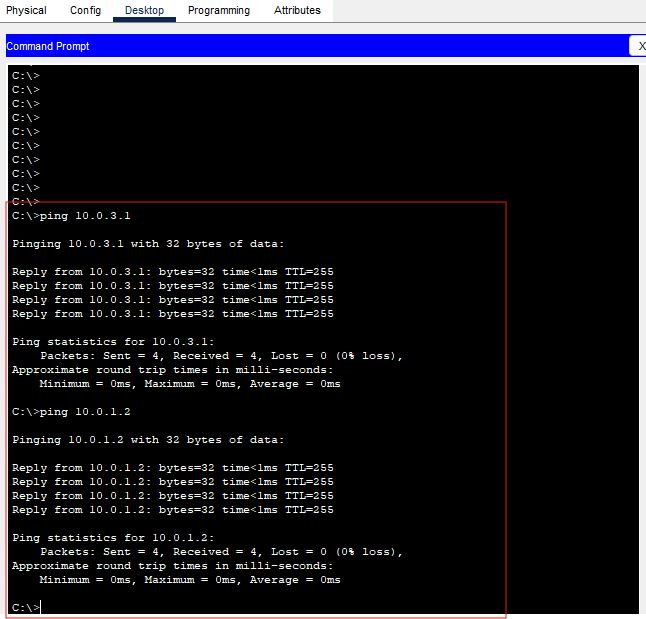
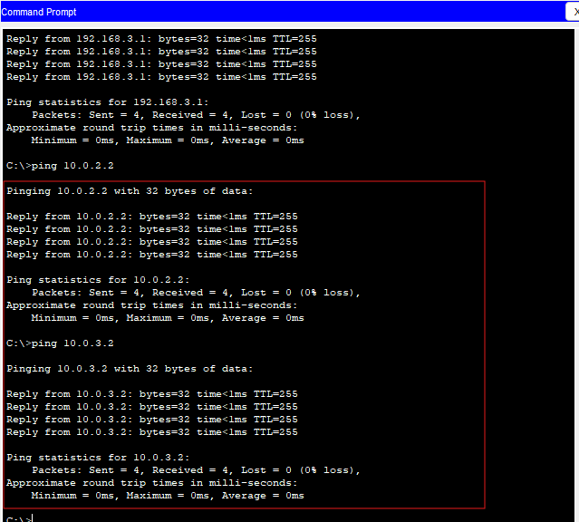
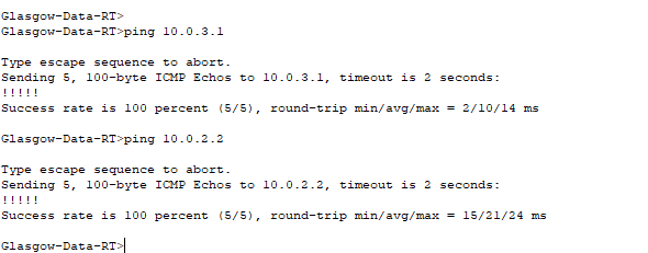
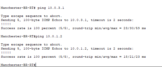
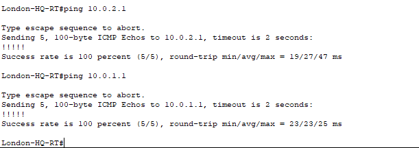
- Test connectivity
We know that our PCs can communicate with each other and the router on their LAN site. Now let's test to see if our PCs can ping the WAN link and if the routers can ping each other.
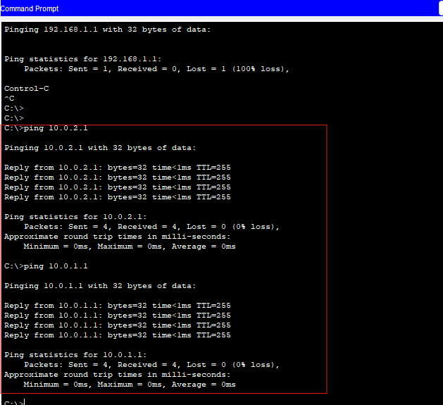
We have completed our setup for this post. We now have the base of our new enterprise network.
By completing this setup, we now have three connected sites with basic IP configurations and WAN connectivity. In the next post, we'll introduce EIGRP to dynamically manage routing between sites and optimize connectivity.
I hope you liked this guide and Happy Networking!
Follow the next post of the series here: