How RIP Shares Routes in a Small Network

When you're managing a network with just a few routers, static routes might be enough. But as your network grows, manually configuring routes on every device becomes time-consuming, error-prone, and hard to maintain.
That's where dynamic routing protocols come into effect. RIP is an old but golden one and is the best one to start with.
In this lab, we'll set up a small multi-router network and configure Routing Information Protocol (RIP) to automatically share routes between devices. You'll see how routers exchange network information, update their routing tables, and adapt to changes without needing constant input.
Requirements
- 3 Cisco routers 2911
- 2 PCs
- Ethernet cables
IP address Information
Each router will be in a different network, and we'll use RIP to let them discover and share those routes dynamically.
| Device/Interface | IP Address | Subnet |
|---|---|---|
| PC0 | 172.16.10.10 | 255.255.255.0 |
| PC1 | 172.16.20.10 | 255.255.255.0 |
| R1 G0/0 | 172.16.10.1 | 255.255.255.0 |
| R1 G0/1 | 172.16.100.1 | 255.255.255.252 |
| R2 G0/1 | 172.16.100.2 | 255.255.255.252 |
| R2 G0/2 | 172.16.200.1 | 255.255.255.252 |
| R3 G0/1 | 172.16.200.2 | 255.255.255.252 |
| R3 G0/0 | 172.16.20.1 | 255.255.255.0 |
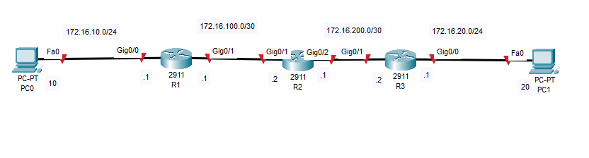
Step 1: Set up The Topology
- Add 3 routers (R1, R2, R3) and 2 PCs (Pc0, Pc1)
- Connect:
- PC0 —> R1 (G0/0)
- R1 (G0/1) <—> R2 (G0/1)
- R2 (G0/2) <—> R3 (G0/1)
- R3 (G0/0) —> PC1
Your Lab should look something like this:
Step 2: Assign IP Addresses
Configure each interface with the correct IP address and subnet. This allows basic communication between directly connected devices.
PC0:
- IP: 172.16.10.10
- Subnet Mask: 255.255.255.0
- Default Gateway: 172.16.10.1
PC1:
- IP: 172.16.20.10
- Subnet Mask: 255.255.255.0
- Default Gateway: 172.16.20.1
R1:
enable
configure terminal
interface g0/0
ip address 172.16.10.1 255.255.255.0
no shutdown
exit
interface g0/1
ip address 172.16.100.1 255.255.255.0
no shutdown
exit
exit
write memory
G0/0 connects to PC0, and G0/1 connects to R2
R2:
enable
configure terminal
interface g0/1
ip address 172.16.100.2 255.255.255.252
no shutdown
exit
interface g0/2
ip address 172.16.200.1 255.255.255.252
no shutdown
exit
exit
write memory
R2 connects to both R1 and R3 using two point-to-point /30 subnets.
R3:
enable
configure terminal
interface g0/1
ip address 172.16.200.2 255.255.255.252
no shutdown
exit
interface g0/0
ip address 172.16.20.1 255.255.255.0
no shutdown
exit
exit
write memory
G0/0 goes to PC1. G0/1 links back to R2.
Step 3: Configure RIP on Each Router
We'll now enable RIP version 2 and advertise the networks directly connected to each router. We also use no auto-summary, so RIP doesn't summarize based on default classful boundaries.
R1:
enable
configure terminal
router rip
version 2
no auto-summary
network 172.16.10.0
network 172.16.100.0
exit
exit
write memory
R2:
enable
configure terminal
router rip
version 2
no auto-summary
network 172.16.100.0
network 172.16.200.0
exit
exit
write memory
R3:
enable
configure terminal
router rip
version 2
no auto-summary
network 172.16.200.0
network 172.16.20.0
exit
exit
write memory
These network commands tell the router to enable RIP on interfaces within those subnets, and start sending/receiving routing updates.
Step 4: Verify RIP is Working
After a few moments, the routers should exchange updates. Check this with:
show ip route
You should see RIP-learned routed marked with the letter R to networks not directly connected.
Here is an example on R2. We can see that 172.16.10.0/24 & 172.168.20.0 is being routed via RIP
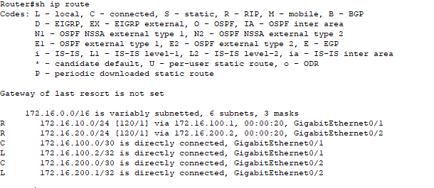
This means that R2 has automatically learned the routes to pass traffic from R1 and R3
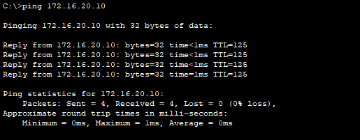
Step 5: Test End-to-End Connectivity
Now we can test the configuration by pinging across the network
From PC0:
ping 172.16.20.10
From PC1:
ping 172.16.10.10
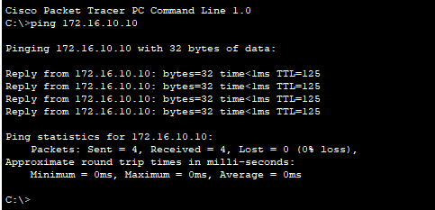
Both PCs are able to ping each other. We know now that RIP is working as intended.
To confirm how the data is traveling from PC1 to PC0, we can run the following command on PC1
tracert 172.16.10.10
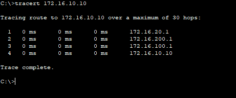
This shows us that the packet is:
- Hitting the default gateway 172.16.20.1 on R3
- Going to R2 interface at 200.1
- Passing to R1 interface on 100.1
- Then terminating at 172.16.10.10 which is PC1
Conclusion
In this lab, we set up a simple but effective network using RIP version 2 to dynamically share routing information between three routers. Instead of adding static routes, we let the routers talk to each other, discovering and updating routes automatically as the network changes.
RIP is simple, but it introduces core concepts you'll see again in more advanced protocols like EIGRP and OSPF.
I hope you enjoyed this guide and Happy Networking!