Configuring EtherChannel with LCAP Between Two Switches
It's common to connect switches using multiple cables to improve redundancy and bandwidth. However, without proper configuration, this can lead to loops, broadcast storms, and blocked ports due to Spanning Tree Protocol (STP)
That's where EtherChannel with LACP (Link Aggregation Control Protocol) comes in. It lets you bundle multiple physical links into one logical link that's loop-free, redundant, and load-balanced and best of all, STP treats it as a single path.
In this lab, we will configure EtherChannel using LACP between two switches. You'll learn how to combine interfaces, configure negotiation, and see how STP interacts with the channel.
Requirements
- 2x 2960 Cisco Switches
- 2x Ethernet cable
Step 1: Connect the Switches
Use the straight-through cable between:
- Fa0/1 and Fa0/2 on Switch 1
- to Fa0/1 and Fa0/2 on Switch 2
Your topology should look something like this:
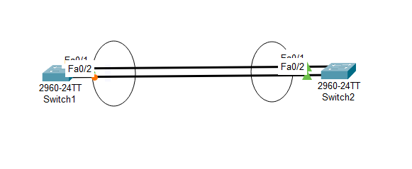
Don't worry about the circles, I just put them in there so I know they are going to be EtherChannels.
Step 2: Create the EtherChannel Group
We'll configure LACP with mode active and mode passive
On Switch 1:
enable
configure terminal
interface range fa0/1-2
channel-group 1 mode active
exit
exit
write memory
On Switch 2:
enable
configure terminal
interface range fa0/1-2
channel-group 1 mode passive
exit
exit
write memory
LACP requires at least one side to be active. Active tries to negotiate, while passive waits for the other side.
Step 3: Configure the Port-Channel Interface
Now we can configure the logical interface created by EtherChannel
On Both Switches:
enable
configure terminal
interface port-channel 1
switchport mode trunk
exit
exit
write memory
This trunk allows VLAN traffic to flow between switches across the bundled links.
Step 4: Verify EtherChannel
Use this commands to check if the bundle is up:
show etherchannel summary
You should see something like:
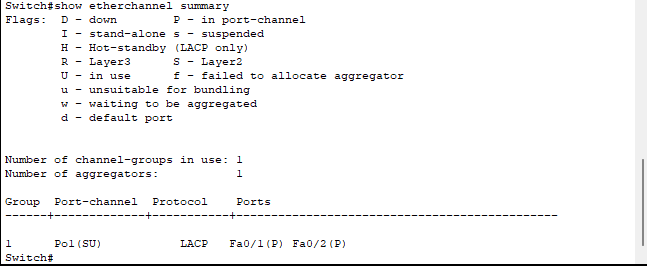
This states:
- Po1: Port-channel 1
- SU: Layer 2, in use
- P: Port is bundled in the channel
Step 5: Verify STP Sees One Link
Let's see what Spanning-tree is saying to us.
show spanning-tree
You should only see one active forwarding link, STP sees the EtherChannel as a single logical connection.
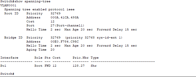
- Port 27 (Port-channel1) Is being used as the forwarding interface.
- Role: Root - This switch see Po1 as the best path toward the root bridge.
- Sts: FWD - The link is forwarding traffic.
- Cost: 12 - The total STP Path cost for this logical link
Conclusion
We have built a stable and redundant link between two switches using EtherChannel with LCP. We have tested it and saw how STP treats the bundle as a single logical interface.
I hope you enjoyed this guide and Happy Networking!