How to Configure a DHCP Server in Cisco Packet Tracer
Managing a medium-sized office with dozen of devices, all needing IP addresses, assigning static IPs manually is not only time-consuming but also prone to errors. This is where DHCP (Dynamic Host Configuration Protocol) comes in.
A DHCP server automatically assigns IP addresses, gateways. And other essential information to devices on your network, simplifying management and reducing human error.
In this guide, we'll set up a DHCP server in Cisco Packet Tracer and configure a small network where IP addresses are dynamically assigned to devices in multiple subnets.
- Topology Overview
- 1 Router (acting as the DHCP server)
- 1 switch
- 3 PCs (clients, one in each subnet
Subnets
|
Department |
Subnet |
Default Gateway |
Range |
|
Sales |
192.168.10.0/24 |
192.168.10.1 |
192.168.10.2 - 192.168.10.254 |
|
HR |
192.168.20.0/24 |
192.168.20.1 |
192.168.20.2 - 192.168.20.254 |
|
IT |
192.168.30.0/24 |
192.168.30.1 |
192.168.30.2 - 192.168.30.254 |
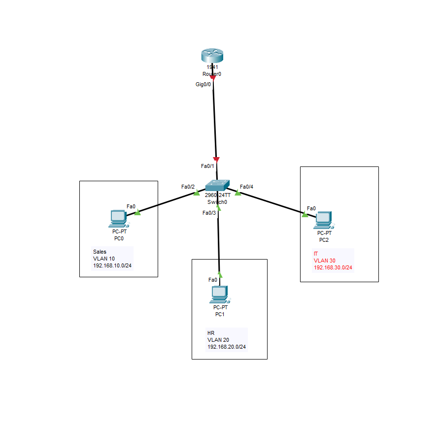
- Build the Topology
Drag and drop the devices on the platform:
- Add 1 router - 1941
- Add 1 switch - 2960
- Add 1 PC for each department
Connect device:
- Use the Ethernet cabled to connect:
- Sales PC: Fast Ethernet port 2
- HR PC: Fast Ethernet port 3
- IT PC: Fast Ethernet port 4
- Switch to the router using port 1 and router port Gigabit Ethernet 0/0
- I like to put a rectangle table to border my PCs to separate them in three different departments.
You should have something like this:
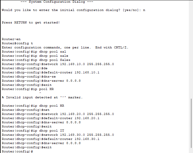
- Configure the Router as a DHCP Server
Click on the router and go to the CLI option, type "no" to bypass the wizard and then press enter.
We need to define the pools for each subnet:
Router> enable
Router# configure terminal

! DHCP Pool for Sales
Router(config)# ip dhcp pool Sales
Router(dhcp-config)# network 192.168.10.0 255.255.255.0
Router(dhcp-config)# default-router 192.168.10.1
Router(dhcp-config)# dns-server 8.8.8.8
Router(dhcp-config)# exit

! DHCP Pool for HR
Router(config)# ip dhcp pool HR
Router(dhcp-config)# network 192.168.20.0 255.255.255.0
Router(dhcp-config)# default-router 192.168.20.1
Router(dhcp-config)# dns-server 8.8.8.8
Router(dhcp-config)# exit

! DHCP Pool for IT
Router(config)# ip dhcp pool IT
Router(dhcp-config)# network 192.168.30.0 255.255.255.0
Router(dhcp-config)# default-router 192.168.30.1
Router(dhcp-config)# dns-server 8.8.8.8
Router(dhcp-config)# exit
It should look something like this:
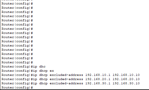
Next, what we want to do is reserve some IPs, as we want to reserve some for the gateways.
Router(config)# ip dhcp excluded-address 192.168.10.1 192.168.10.10
Router(config)# ip dhcp excluded-address 192.168.20.1 192.168.20.10
Router(config)# ip dhcp excluded-address 192.168.30.1 192.168.30.10
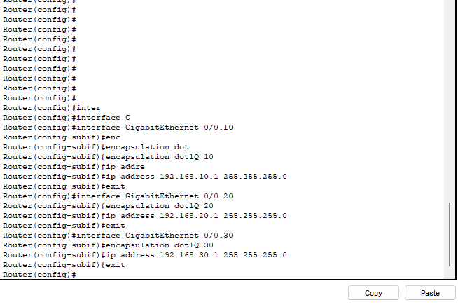
- Configure Interfaces on the Router
We are going to be configuring sub-interfaces for each VLAN
Router(config)# interface GigabitEthernet0/0.10
Router(config-subif)# encapsulation dot1Q 10
Router(config-subif)# ip address 192.168.10.1 255.255.255.0
Router(config-subif)# exit

Router(config)# interface GigabitEthernet0/0.20
Router(config-subif)# encapsulation dot1Q 20
Router(config-subif)# ip address 192.168.20.1 255.255.255.0
Router(config-subif)# exit

Router(config)# interface GigabitEthernet0/0.30
Router(config-subif)# encapsulation dot1Q 30
Router(config-subif)# ip address 192.168.30.1 255.255.255.0
Router(config-subif)# exit
We now need to bring the physical interface up. We can do this by:
Router(config)# interface GigabitEthernet0/0
Router(config-if)# no shutdown
Router(config-if)# exit
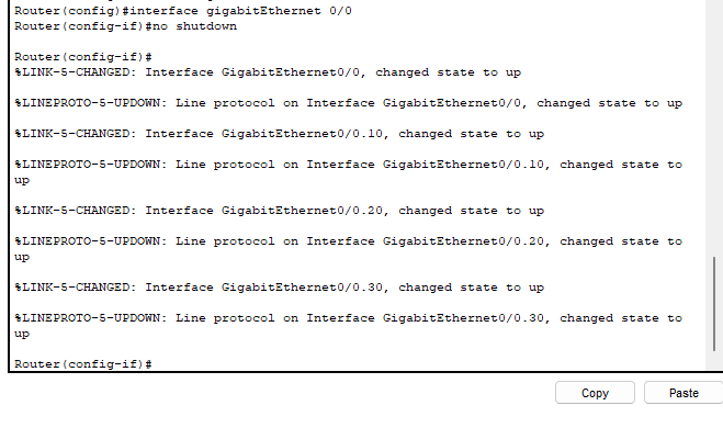
We can see above that the interfaces has changed state to up.
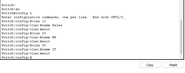
- Configure VLANs on the switch
Click on the switch and go to CLI and press enter.
Switch> enable
Switch# configure terminal
Switch(config)# vlan 10
Switch(config-vlan)# name Sales
Switch(config)# vlan 20
Switch(config-vlan)# name HR
Switch(config)# vlan 30
Switch(config-vlan)# name IT
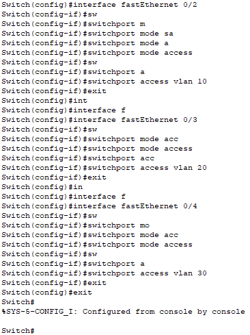
Now we need to assign the ports to the VLANs:
Switch(config)# interface FastEthernet0/2
Switch(config-if)# switchport mode access
Switch(config-if)# switchport access vlan 10

Switch(config)# interface FastEthernet0/3
Switch(config-if)# switchport mode access
Switch(config-if)# switchport access vlan 20

Switch(config)# interface FastEthernet0/4
Switch(config-if)# switchport mode access
Switch(config-if)# switchport access vlan 30
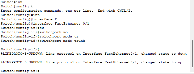
We now need to configure the trunk port from the switch to the router:
Switch(config)# interface Fast Ethernet0/1
Switch(config-if)# switchport mode trunk
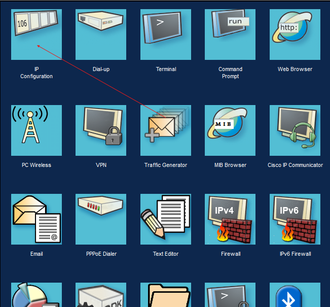
- Test DHCP Configuration
On each PC, go to the Desktop tab > IP Configuration
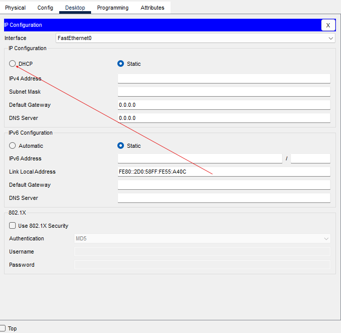
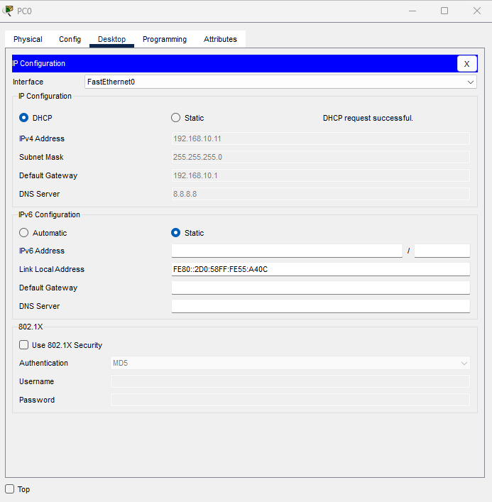
Do the above for the rest of the PCs, make sure that all of them are getting the correct subnet ranges setup for their VLANs.
- Test Connectivity
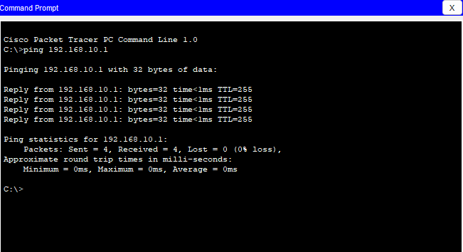
Now that the PCs have their IP addresses allocated to them by the DHCP, let's see if they can ping their default gateway and each other.
I am going to use PC0 in Sales to test.
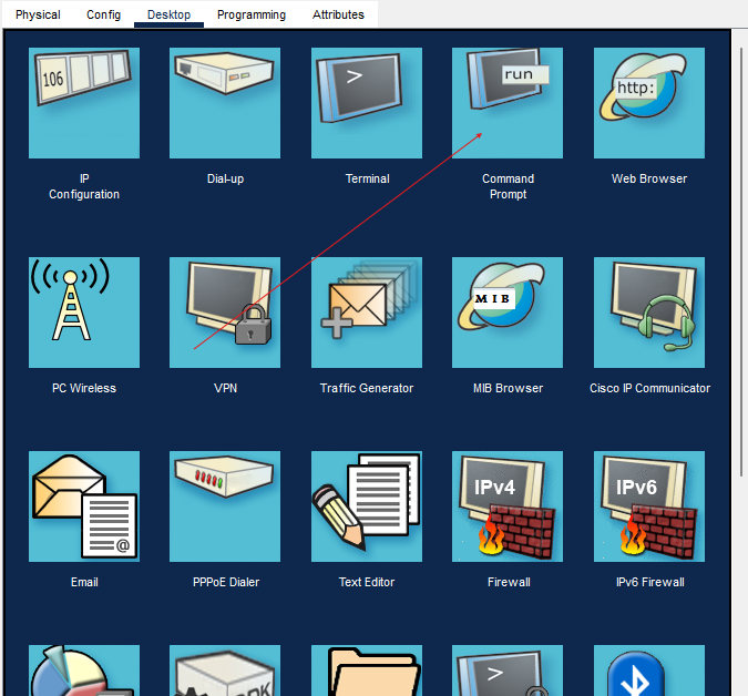
Go to Desktop > Command Prompt
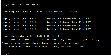
Can I ping PC 2 in IT on 192.168.30.11 ?
Conclusion
We have configured a router to act as a DHCP server and dynamically assigned IP addresses to devices in multiple VLANs. This setup reduces the manual overhead of assigning IPs but also ensures scalability and efficiency in managing network resources.
Hope this guide was helpful, and Happy Networking!