Setting up a Voice VLAN with DHCP and Phone Extensions

In the real-world environments, IP phones and computers share the same switch but operate on separate VLANs. This setup improves security, performance, and network manageability. Especially in offices where VoIP is the main form of communication.
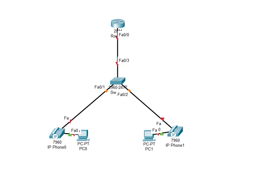
In this lab, we will simulate a small office network where we need to set up a Voice VLAN with DHCP and internal calling. We'll configure a router to provide IP addresses via DHCP, segment the network with a dedicated Voice VLAN, and connect IP phones to a switch. Each phone will receive an IP address from the voice pool and be assigned an extension number.
Once everything is configured, we will test the set-up by having one phone call another using its extension number like an actual office environment.
Requirements
- 1x 2811 Cisco router
- 1x 2960 Cisco Switch
- 2x PCs (Pc0 & PC1)
- Ethernet cable
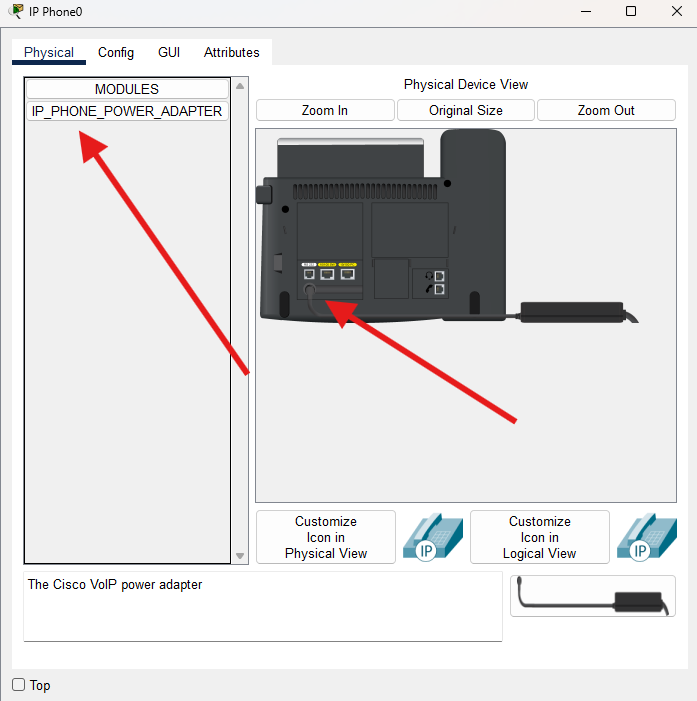
We are using 2960 switches as they do not support PPOE so we will need to drag the power module on the phones to start them up.
Your topology should look something like this:
Step 1: Create the Voice VLAN
On the switch, create VLAN 30 for voice traffic
  enable
  configure terminal
  vlan 30
  name Voice-VLAN
  exit
  exit
  write memory
Step 2: Configure Switch Ports for IP Phones
Each port connected to a phone should support both a phone and an attached PC. Use the switchport voice vlan command
enable
configure terminal
interface range fa0/1 - 2
switchport access vlan 1
switchport voice vlan 30
exit
interface f0/3
switchport mode trunk
exit
exit
write memory
This configures each port as an access port for PCs using the default VLAN 1 and tags voice traffic for VLAN 30. The phone will use VLAN 30, and any PC connected to the phone will use VLAN 1.
Step 3: Configure DHCP on the Router
The router will provide IP addresses to the phones though a DHCP pool.
enable
configure terminal
ip dhcp pool VOICE
network 192.168.30.0 255.255.255.0
default-router 192.168.30.1
option 150 ip 192.168.30.1
dns-server 8.8.8.8
exit
interface f0/0.30
encapsulation dot1Q 30
ip address 192.168.30.1 255.255.255.0
exit
inteface f0/0
no shutdown
exit
write memory
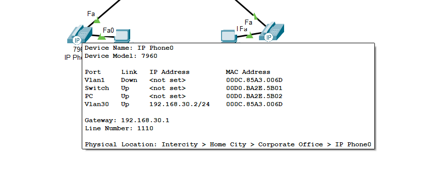
Now the option 150 ip 192.168.30.1 tells the IP phones to use 192.168.30.1 as a TFTP server, TFTP is used by IP phones to download their configuration files. This includes their firmware, extensions, and call Manager settings.
We should see an IP address being allocated to the phones by hovering over the phone.
Step 4: Configure Call Manager on the Router
In packet Tracer, extension numbers are handled through a basic Call Manager Express (CME) service built into supported routers. For example, the 2811 allows us to do this. You'll need to set up a telephony service before the extensions can work.
Enable telephony service on the router.
enable
configure terminal
telepony-service
max-ephones 2
max-dn 2
ip source-address 192.168.30.1 port 2000
exit
ephone-dns 1
number 1110
exit
ephone-dns 2
number 1120
exit
ephone 1
type 7960
button 1:1
exit
ephone 2
type 7960
button 1:2
exit
exit
write memory
I will break the commands we are using down, as there is a bit to configure here.
telepony-service
max-ephones 2
max-dn 2
ip source-address 192.168.30.1 port 2000
- telepony-service – We are activating the Cisco call Manager on the Router
- max-ephones 2 – Allows up two IP phones (ephones) to register to the CME
- max-dn 2 – Allows two directory numbers (extensions)
- ip source-address port 2000 – Use IP address 192.168.30.1 and UDP port 2000 for managing SCCP communication with IP Phones.
ephone-dns 1
number 1110
exit
ephone-dns 2
number 1120
exit
- ephone-dns 1 – Opens phone 1 directory
- number 1110 – Adds extension 1110 to directory 1
ephone 1
type 7960
button 1:1
exit
ephone 2
type 7960
button 1:2
- ephone 1 – Open phone 1
- type 7960 – Add in model of the phone
- button 1:1 – On button 1 link it to ephone-dn 1
Step 5: Testing Internal calls Work
Now we can test to see if the phones have the correct extension numbers linked to the phones.
We may need to reboot the phone, as sometimes the extension does not get passed to the phone straight away, so a reboot may solve this. Just drag the power module off the phone and back on again, and wait for the phone to boot up.
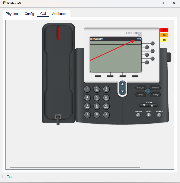
If we go to the GUI section, we should see an extension number on the phone.
Now we can call the other phone's extension number 1120 to see if the phone rings, and we can pick up to complete the connection. Just type in the number and press the handset to start the call.
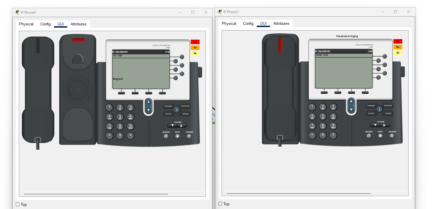
We can see that phone 1 is calling phone 2 and phone 2's handset is flashing red.
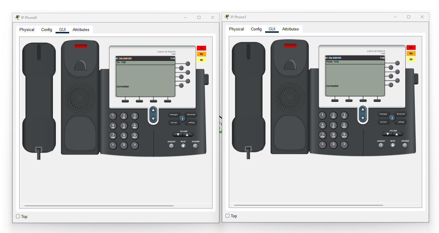
Once we pick up phone 2, we can see that a connection has established on the both phones.
Conclusion
In this lab, we have configured a dedicated Voice VLAN, built a DHCP service, and enabled two IP phones to communicate using extensions.
Getting voice working in a network setup isn't just about plugging in phones, it's about understanding how different technologies like VLANs, DHCP and Call Manager Express all come together.
I hope you like this guide and Happy Networking!