Step-by-Step Guide: VLANs and Inter-VLAN Routing in Cisco Packet Tracer

Imagine you're setting up a small office network with three departments: Sales, HR and IT. Each department needs its own isolated network for security and efficiency, but they also need to communicate with each other for tasks like sharing files or accessing shared resources. This is where VLANs (Virtual Local Area Networks) and inter-VLAN routing comes into play.
VLANs are a powerful way to segment your network. By creating separate VLANs for each department, you can:
- Improve security by isolating network traffic for each group.
- Enhance efficiency by reducing unnecessary broadcast traffic
- Simplify network management, especially in environments with multiple teams or departments
In this guide, I'll show you how to set up VLANS and configure inter-VLAN routing in Cisco Packet Tracer step-by-step.
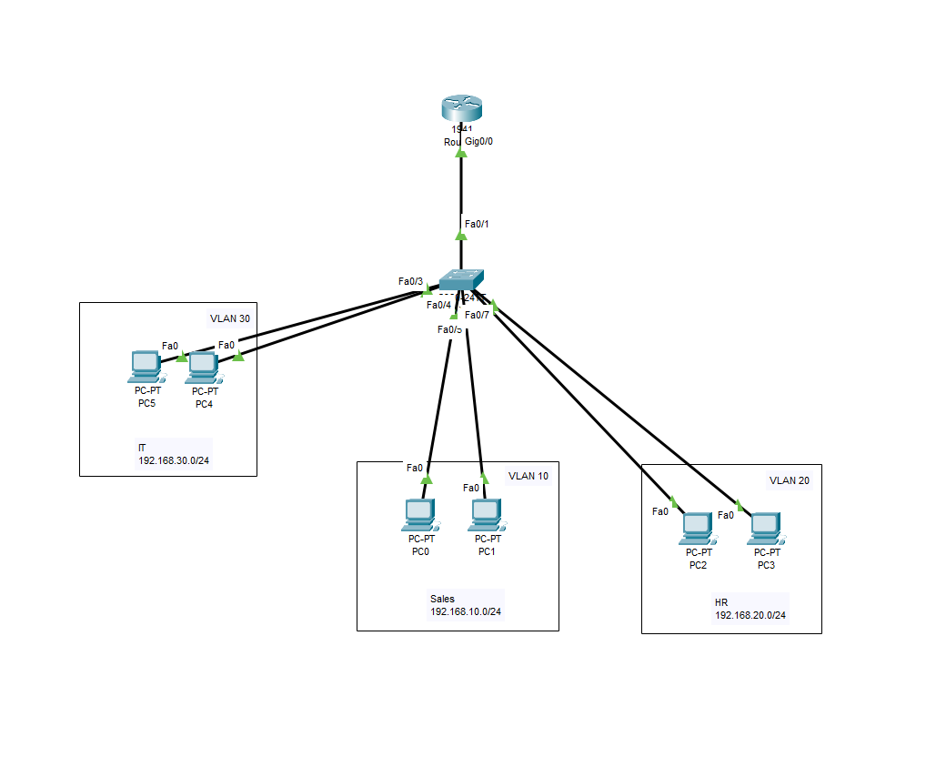
- Topology Overview
- 1 Router (for inter-VLAN routing)
- 1 Switch
- 6 Pcs
|
VLAN |
Department |
VLAN ID |
Subnet |
Default Gateway |
|
VLAN 10 |
Sales |
10 |
192.168.10.0/24 |
192.168.10.1 |
|
VLAN 20 |
HR |
20 |
192.168.20.0/24 |
192.168.20.1 |
|
VLAN 30 |
IT |
30 |
192.168.30.0/24 |
192.168.30.1 |
- Build the Topology
Drag and drop the devices on to the platform:
- Add 1 router - 1941
- Add 1 switch - 2960
- Add 6 PCs (3 departments, 2 PCs per department)
Connect device:
- Use the Ethernet cable to connect:
- IT PCs: Fast Ethernet 2 -3
- Sales Pcs: Fast Ethernet 4–5
- HR PCs: Fast Ethernet 6-7
- Switch to the router using the first port, Fast Ethernet 0/1 and Gigabit Ethernet 0/0.
- I like to put a rectangle table to border my PCs to separate them in three different departments
You should have something like this: The lights on your cables may be red, however, as we have not configured the switch or router.
- Switch configuration
Click on the switch and go to the CLI section. Press enter and start to type the commands below.
Switch> enable
Switch# configure terminal
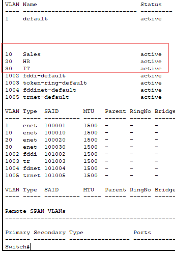
Switch(config)# vlan 10
Switch(config-vlan)# name Sales
Switch(config-vlan)# exit
Switch(config)# vlan 20
Switch(config-vlan)# name HR
Switch(config-vlan)# exit
Switch(config)# vlan 30
Switch(config-vlan)# name IT
Switch(config-vlan)# exit
With a show vlan command, we can see our newly created VLANS
Assign VLANS to Ports
- Assign switch ports to specific VLANs:
Switch(config)# interface range FastEthernet0/2-3
Switch(config-if-range)# switchport mode access
Switch(config-if-range)# switchport access vlan 30
Switch(config-if-range)# exit

Switch(config)# interface range FastEthernet0/4-5
Switch(config-if-range)# switchport mode access
Switch(config-if-range)# switchport access vlan 10
Switch(config-if-range)# exit

Switch(config)# interface range FastEthernet0/6-7
Switch(config-if-range)# switchport mode access
Switch(config-if-range)# switchport access vlan 20
Switch(config-if-range)# exit
Configure the Trunk Port:
Configure the port connecting the switch to the router as a trunk. We want to do this to enable inter-VLAN communication, because a trunk port can carry traffic for multiple VLANS simultaneously. It uses encapsulation to tag frames with VLAN IDs so that devices can either side of the trunk distinguish traffic from different VLANs.
Switch(config)# interface GigabitEthernet0/1
Switch(config-if)# switchport mode trunk
Switch(config-if)# exit
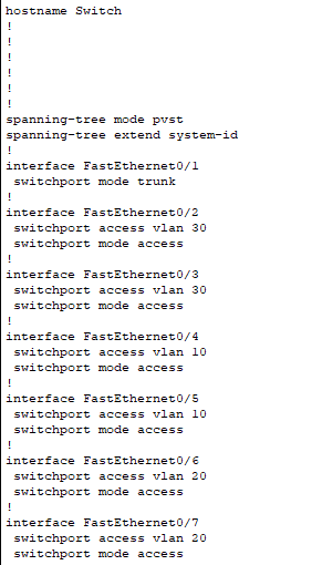
If we so a show run and scroll down to the interfaces, we can see the interfaces and the VLANs added to them with the switchport mode access.
- Configure the Router
We need to create Sub-interfaces for Inter-VLAN routing:
- Click on the router and go to CLI
- Enable sub-interfaces for each VLAN on the trunk port
Router> enable
Router# configure terminal
Router(config)# interface GigabitEthernet0/0.10
Router(config-subif)# encapsulation dot1Q 10
Router(config-subif)# ip address 192.168.10.1 255.255.255.0
Router(config-subif)# exit

Router(config)# interface GigabitEthernet0/0.20
Router(config-subif)# encapsulation dot1Q 20
Router(config-subif)# ip address 192.168.20.1 255.255.255.0
Router(config-subif)# exit

Router(config)# interface GigabitEthernet0/0.30
Router(config-subif)# encapsulation dot1Q 30
Router(config-subif)# ip address 192.168.30.1 255.255.255.0
Router(config-subif)# exit
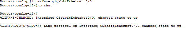
Enable the Router's Physical interface:
We need to make sure that the physical interface is up. After doing this command, you should see the links on your cables go from red to green.
Router(config)# interface GigabitEthernet0/0
Router(config-if)# no shutdown
Router(config-if)# exit
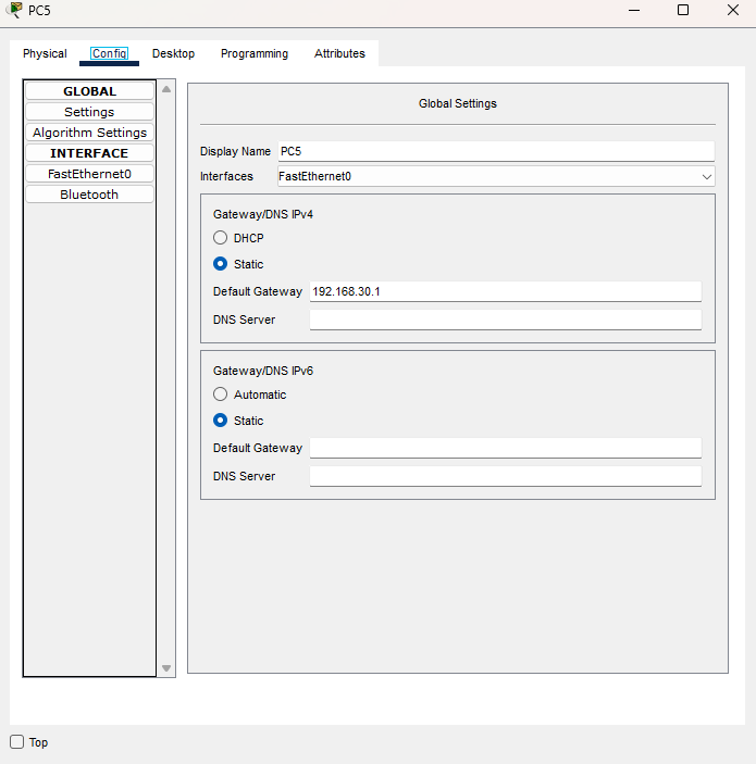
- Configure PCs
Because we are not adding DHCP onto this router in this guide or setting a DHCP server, we will need to manually configure our PCs.
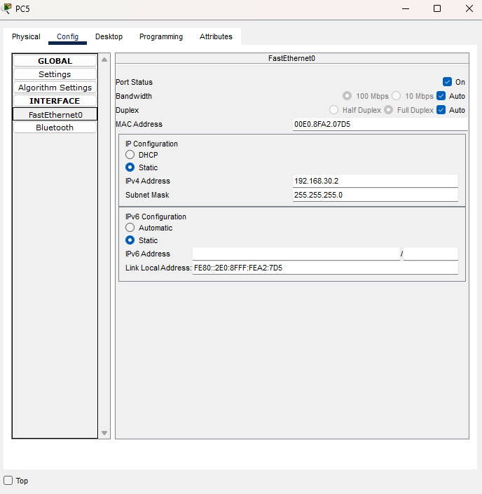
Click the PCs and go to config > Interface and Fast Ethernet.
- Sales PCs (VLAN 10):
- PC0: 192.168.10.2/24, Gateway: 192.168.10.1
- PC1: 192.168.10.3/24, Gateway: 192.168.10.1
- HR PCs (VLAN 20):
- PC2: 192.168.20.2/24, Gateway: 192.168.20.1
- PC3: 192.168.20.3/24, Gateway: 192.168.20.1
- IT PCs (VLAN 30):
- PC4: 192.168.30.2/24, Gateway: 192.168.30.1
- PC5: 192.168.30.3/24, Gateway: 192.168.30.1
- Pinging PCs
We can test our the connection by pinging the default Gateway and the PC within the same VLAN
Ping PC 5 from PC 4 in the IT department.

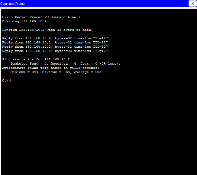
Next, ping PC4 in IT to PC2 in HR to see if the inter-VLAN is working.
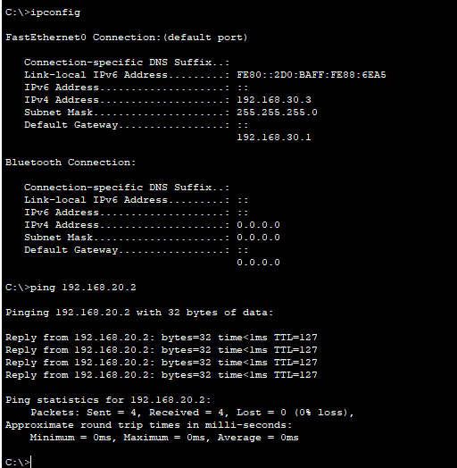
We can see above that the inter-VLAN we set up is working. All devices can communicate with each other, yet they are on different VLANs.
Conclusion
In this guide, we've walked through the process of setting up VLANs and configured inter-vlan routing in Cisco Packet Tracer. By segmenting your network into VLANs, you've improved security, reduced unnecessary broadcast traffic, and laid the groundwork for efficient network management.
Through Inter-VLAN routing, you've enabled communication between departments while maintaining the benefits of segmentation.
Hope this guide was helpful and Happy Networking!